Tolerance Analysis
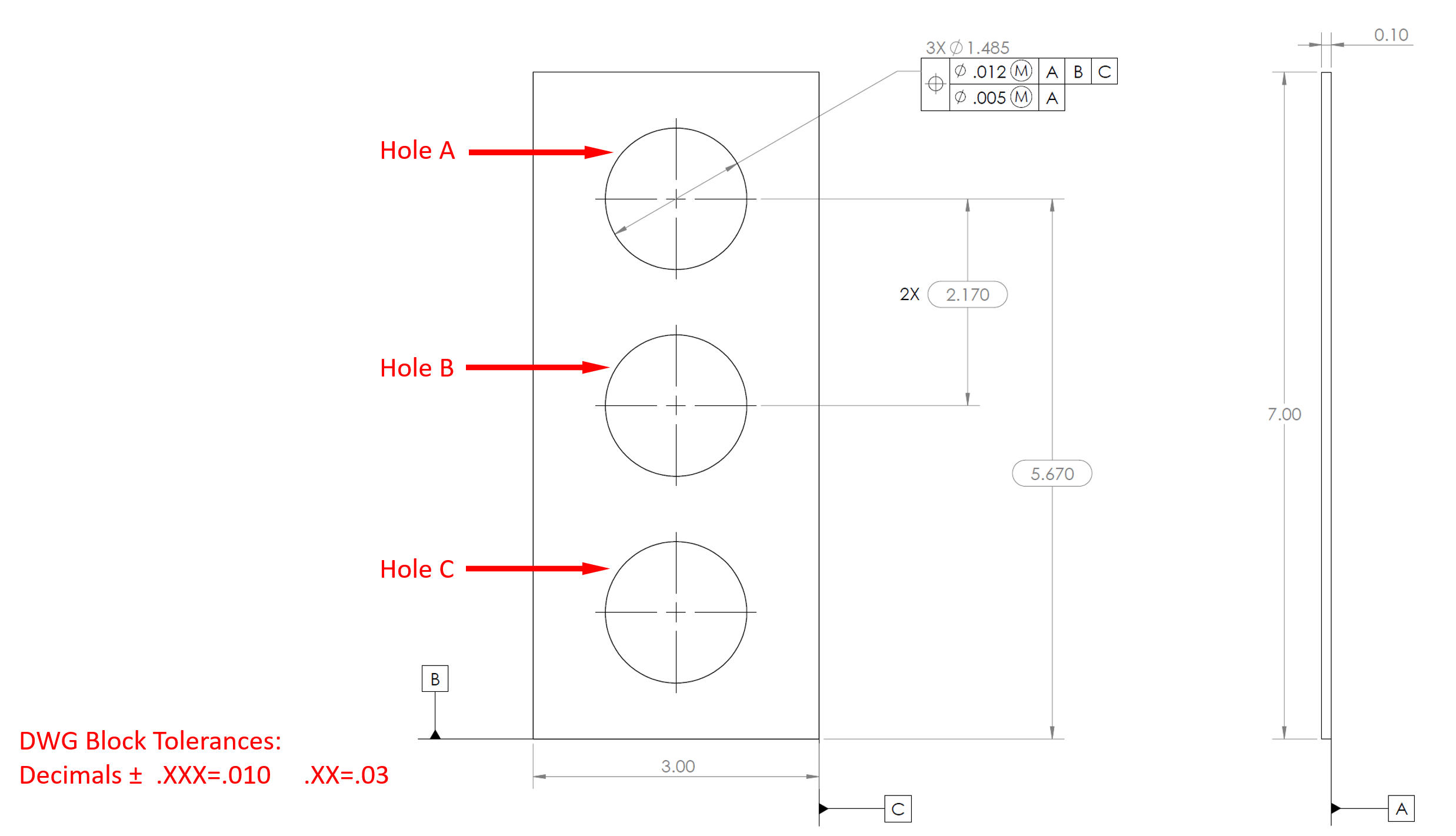
Consider the below drawing of a front panel plate cutout. Assume the 3 holes line up perfectly along the vertical centerline.
- What is the largest vertical spacing allowed between Holes B and C?
- What is the largest diameter allowed for Hole B?
- What is the smallest distance allowed between Hole A and Datum B?

Expand Hint
All the basic dimensions are controlled by the Composite Positional Tolerance. All bilateral dimensions are controlled by the block tolerances.
Hint 2
The tolerances will determine how much you subtract/add between dimensions. The question is basically asking the min and max distances/diameter.
-
The vertical spacings between holes A-B and B-C are controlled by the "2X 2.170" dimension, and are identical. Because "2.170" is a basic dimension, the Composite Positional Tolerance associated with the Hole A diameter callout will dictate the max range. The upper segment dictates the positional tolerance of Hole A relative to Datum B, while the lower segment determines the tolerance for the spacings between all three holes.
$$$2.170+(.005/2)=2.1725\:max\:distance$$$
-
The "3X ⌀1.485" callout for Hole A is a bilateral dimension that controls the diameters for all three holes. As a result, the drawing block tolerance controls this feature. Because the "⌀1.485" callout has three decimal places:
$$$1.485+.010=1.495\:max\:diameter$$$
- The spacing between Hole A and Datum B is controlled by the "5.670" dimension. Because "5.670" is a basic dimension, the Composite Positional Tolerance associated with the Hole A diameter callout will dictate the max distance. The upper segment dictates the positional tolerance of Hole A relative to Datum B, while the lower segment determines the tolerance for the spacings between all three holes.
$$$5.670-(.012/2)=5.664\:min\:distance$$$
- 2.1725 max distance
- 1.495 max distance
- 5.664 min distance
Time Analysis
See how quickly you looked at the hint, solution, and answer. This is important for making sure you will finish the FE Exam in time.- Hint: Not clicked
- Solution: Not clicked
- Answer: Not clicked
Similar Problems from FE Sub Section: Modifying Symbols
053. GD&T
215. Positional Tolerance
402. GTOL
404. Feature Control Frame
409. GDT Symbols
411. GDT Rule #1
414. GTOL Rule #1
415. Geometric Symbols
417. ASME Y14.5 Symbols
421. RFS Boundaries
422. LMC Boundaries
423. MMC Boundaries
425. A Hole’s Virtual Size
426. A Pin’s Virtual Size
427. MMC Hole’s Virtual Size
428. MMC Pin’s Virtual Size
438. Accept or Reject?
Similar Problems from FE Section: Geometric Dimensioning and Tolerancing (GD&T)
053. GD&T
092. MMC vs LMC
215. Positional Tolerance
398. MMC & LMC
402. GTOL
404. Feature Control Frame
409. GDT Symbols
411. GDT Rule #1
414. GTOL Rule #1
415. Geometric Symbols
417. ASME Y14.5 Symbols
421. RFS Boundaries
422. LMC Boundaries
423. MMC Boundaries
425. A Hole’s Virtual Size
426. A Pin’s Virtual Size
427. MMC Hole’s Virtual Size
428. MMC Pin’s Virtual Size
438. Accept or Reject?