ASME Y14.5 Symbols
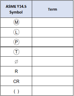
Label the associated term for the shown ASME Y14.5 symbols.
Expand Hint
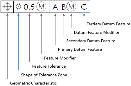
Recall the symbols you may have seen in a feature control frame.
Hint 2
A lot of these self-explanatory symbols are commonly found next to dimensions on drawings.

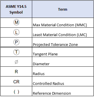
MMC modifier is the condition in which a feature of size contains the maximum amount of material within the stated limits of size. LMC modifier describes a size condition in which the least amount of material exists within its dimensional tolerance. The projected tolerance zone modifier applies to a feature’s protrusion. It usually limits how far a pin or dowel can stick out of a body in an assembly drawing. The tangent plane modifier creates a boundary plane against only the high points of a surface, rather than every point along that surface. The symbols used to indicate diameter, radius, and controlled radius shall precede the value of a dimension or tolerance given as a diameter or radius, as applicable. Dimensions enclosed by parentheses are reference dimensions. They are added to some views for clarity, but the requirement(s) is driven/called out elsewhere on the drawing.
Time Analysis
See how quickly you looked at the hint, solution, and answer. This is important for making sure you will finish the FE Exam in time.- Hint: Not clicked
- Solution: Not clicked
- Answer: Not clicked
Similar Problems from FE Sub Section: Modifying Symbols
053. GD&T
072. Tolerance Analysis
215. Positional Tolerance
402. GTOL
404. Feature Control Frame
409. GDT Symbols
411. GDT Rule #1
414. GTOL Rule #1
415. Geometric Symbols
421. RFS Boundaries
422. LMC Boundaries
423. MMC Boundaries
425. A Hole’s Virtual Size
426. A Pin’s Virtual Size
427. MMC Hole’s Virtual Size
428. MMC Pin’s Virtual Size
438. Accept or Reject?
Similar Problems from FE Section: Geometric Dimensioning and Tolerancing (GD&T)
053. GD&T
072. Tolerance Analysis
092. MMC vs LMC
215. Positional Tolerance
398. MMC & LMC
402. GTOL
404. Feature Control Frame
409. GDT Symbols
411. GDT Rule #1
414. GTOL Rule #1
415. Geometric Symbols
421. RFS Boundaries
422. LMC Boundaries
423. MMC Boundaries
425. A Hole’s Virtual Size
426. A Pin’s Virtual Size
427. MMC Hole’s Virtual Size
428. MMC Pin’s Virtual Size
438. Accept or Reject?