Positional Tolerance
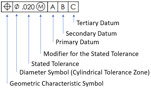
Consider you see the below drawing callout for a part's hole feature. What is its positional tolerance?

Expand Hint
The geometric tolerance is specified in the feature control frame.
Hint 2
Refer to the Geometric Characteristic Symbol and Diameter Symbol within the feature control frame.
The geometric tolerance is specified in the feature control frame.

In our feature control frame, the true position symbol is in our geometric characteristic symbol section, which means we have a .020 positional tolerance.
.020
Time Analysis
See how quickly you looked at the hint, solution, and answer. This is important for making sure you will finish the FE Exam in time.- Hint: Not clicked
- Solution: Not clicked
- Answer: Not clicked
Similar Problems from FE Sub Section: Definitions used in ASME Y14.5
092. MMC vs LMC
398. MMC & LMC
402. GTOL
404. Feature Control Frame
425. A Hole’s Virtual Size
426. A Pin’s Virtual Size
427. MMC Hole’s Virtual Size
428. MMC Pin’s Virtual Size
438. Accept or Reject?
Similar Problems from FE Sub Section: Modifying Symbols
053. GD&T
072. Tolerance Analysis
402. GTOL
404. Feature Control Frame
409. GDT Symbols
411. GDT Rule #1
414. GTOL Rule #1
415. Geometric Symbols
417. ASME Y14.5 Symbols
421. RFS Boundaries
422. LMC Boundaries
423. MMC Boundaries
425. A Hole’s Virtual Size
426. A Pin’s Virtual Size
427. MMC Hole’s Virtual Size
428. MMC Pin’s Virtual Size
438. Accept or Reject?
Similar Problems from FE Section: Geometric Dimensioning and Tolerancing (GD&T)
053. GD&T
072. Tolerance Analysis
092. MMC vs LMC
398. MMC & LMC
402. GTOL
404. Feature Control Frame
409. GDT Symbols
411. GDT Rule #1
414. GTOL Rule #1
415. Geometric Symbols
417. ASME Y14.5 Symbols
421. RFS Boundaries
422. LMC Boundaries
423. MMC Boundaries
425. A Hole’s Virtual Size
426. A Pin’s Virtual Size
427. MMC Hole’s Virtual Size
428. MMC Pin’s Virtual Size
438. Accept or Reject?