MMC Hole’s Virtual Size
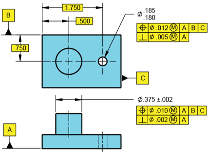
Answer the following questions based on the figure shown.
- What is the hole’s MMC size?
- What is the hole’s Virtual Size relative to Datums ABC?
- What is the hole’s Virtual Size relative to Datum A?

Expand Hint
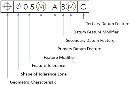
Breaking down the parts of a feature control frame:

Hint 2
The virtual condition is used to analyze the clearance distance between mating parts. It is a constant boundary generated by a combination of a feature of size’s specified MMC or LMC and the geometric tolerance for that material condition.
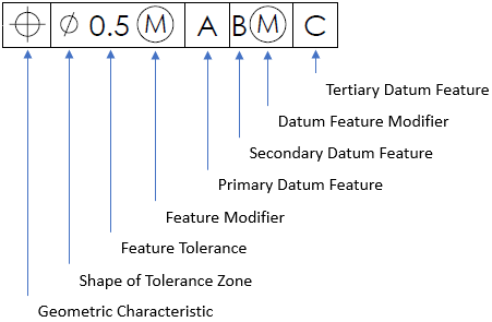
Breaking down the parts of a feature control frame:

The problem statement specifies a Max Material Condition (MMC) feature modifier. A MMC modifier is the condition in which a feature of size contains the maximum amount of material within the stated limits of size. For a hole, MMC is the dimension that produces the smallest cutout. Thus,
$$$MMC_{hole}=.180$$$
The virtual condition is used to analyze the clearance distance between mating parts. It is a constant boundary generated by a combination of a feature of size’s specified MMC or LMC and the geometric tolerance for that material condition. In summary,
For an Internal Feature (Hole) with Geo Tol at MMC:
- Inner Boundary (IB) = MMC (think smallest hole) - geo tol = Virtual Size/Condition
For an External Feature (Pin) with Geo Tol at MMC:
- Outer Boundary (OB) = MMC (think largest pin) + geo tol = Virtual Size/Condition
where
$$geo\:tol$$
is the stated value in the feature control frame.
In the feature control frame, the positional tolerance is the one associated with Datums ABC. Thus, the hole’s virtual size is:
$$$.180-.012=.168$$$
In the feature control frame, the perpendicularity tolerance is the one associated with Datum A only. Thus, the hole’s virtual size is:
$$$.180-.005=.175$$$
- .180
- .168
- .175
Time Analysis
See how quickly you looked at the hint, solution, and answer. This is important for making sure you will finish the FE Exam in time.- Hint: Not clicked
- Solution: Not clicked
- Answer: Not clicked
Similar Problems from FE Sub Section: Definitions used in ASME Y14.5
092. MMC vs LMC
215. Positional Tolerance
398. MMC & LMC
402. GTOL
404. Feature Control Frame
425. A Hole’s Virtual Size
426. A Pin’s Virtual Size
428. MMC Pin’s Virtual Size
438. Accept or Reject?
Similar Problems from FE Sub Section: Modifying Symbols
053. GD&T
072. Tolerance Analysis
215. Positional Tolerance
402. GTOL
404. Feature Control Frame
409. GDT Symbols
411. GDT Rule #1
414. GTOL Rule #1
415. Geometric Symbols
417. ASME Y14.5 Symbols
421. RFS Boundaries
422. LMC Boundaries
423. MMC Boundaries
425. A Hole’s Virtual Size
426. A Pin’s Virtual Size
428. MMC Pin’s Virtual Size
438. Accept or Reject?
Similar Problems from FE Section: Geometric Dimensioning and Tolerancing (GD&T)
053. GD&T
072. Tolerance Analysis
092. MMC vs LMC
215. Positional Tolerance
398. MMC & LMC
402. GTOL
404. Feature Control Frame
409. GDT Symbols
411. GDT Rule #1
414. GTOL Rule #1
415. Geometric Symbols
417. ASME Y14.5 Symbols
421. RFS Boundaries
422. LMC Boundaries
423. MMC Boundaries
425. A Hole’s Virtual Size
426. A Pin’s Virtual Size
428. MMC Pin’s Virtual Size
438. Accept or Reject?